The more I work with the Revit interface, the more the workflow begins to make sense. It is definitely a transition from a CAD based system. In my modeling process, I imported a series of raster images of drawings of Villa Savoye and used them as reference to build my model. Once I set up a logical grid system, it became easier to know where things should be placed (partially because of Le Corbusier’s strict adherence to the grid).


Additionally, the “flat tube” panel type has a parameter called “transition” which allows the designer to control the distance over which the tube goes from round to flattened.

There were a few areas I ran into trouble and on which I had to spend some extra time. The ramp was something I had not worked with previously, and creating the curved curtain wall system was a bit cumbersome. It also took some time to figure out the best way to model the organic wall forms on the top “rooflines” level.

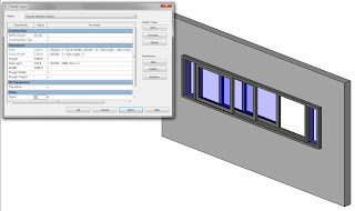
I had to make a few choices as to what I should spend time creating custom objects for and where I should just use an existing family. I decided the custom window was something that needed to be created, as it is an integral part of the design. I created a family whose length, height and sill height could be adjusted to fit any situation. The two outside lights are a function of the overall length, which allows the component to maintain its proportions as its size is altered.

I also made an “instance” parameter allowing the window to be listed as open or closed. This is not necessary for a BIM, but could be useful in rendering if you wanted to show possibilities. The opening is a product of the window array, and simply restricts the length over which the array can take place causing an “open” “closed” or “partially open” scenario. I have restricted this by making it an “On/Off” parameter, thus preventing the “partially open” option from appearing which prevents a user from potentially breaking the model by inputting an incorrect length.

Parametric Family:
My parametric family is for the creation of a façade system of metal tubes. They are variable in height, width, and radius, and can take on the dimensions of any size curtain wall panel.

I actually created a pair of families. One is a direct “tube” family with only the above parameters. The second is a blended geometry that allows the tube to flatten out over a specified distance to create “openings” in the façade system.
Each family actually consists of three nested families. The first is the basic geometry which is modeled in a “generic model” template.


The second is an arrayed set of the nested geometry. The first family passes its parameters to the second and the second determines the number of tubes along a given length by maintaining a spacing which is a function of the radius. This family is a “generic model – linear” family which allows us to reference a back plane in the third family.


The third family is a “curtain wall panel” family. By nesting the linear array into a curtain wall panel, we are able to pass the dimensions of an infinite number of curtain wall panel possibilities through both nested families which allows the project level to control the height, radius, spacing, and number of tubes on any given panel. This works for both “tube” and “flat tube” panel types.


The panels can be arranged in any number of ways in a complex curtain wall system.
No comments:
Post a Comment